Simple Light and Sound Indicator for Mains Power Supply Circuit Diagram How to make a simplest 12v battery full charge indicator circuit at home with simple diagram. Basic 12v car battery full charge status monitor circuit board.
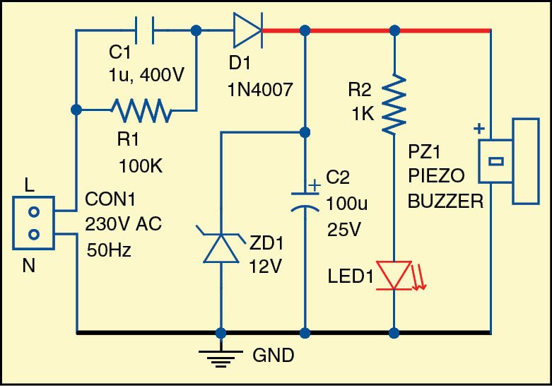
In this easy electronics tutorial, we'll show you how to build a **Reverse Polarity & Fuse Blown Indicator Circuit**. This simple but essential circuit helps
How to Build a Reverse Polarity & Fuse Blown Indicator Circuit Circuit Diagram
In the above design we find that an automatic power failure indication is provided by a single transistor and a small piezo buzzer. Circuit Description. The above power failure indicator circuit design is quite identical to the 1st design using LED and capacitor. Here, instead of the LED we use a piezo buzzer. The design for the AC Line-Voltage Monitor circuit is shown in the above figure. The circuit, as previously noted, is powered by a wall transformer rated at 12 volts DC. Two quad LM324 op-amp ICs (IC1 and IC2) are the heart of the circuit, and they are powered by regulated power from a fixed DC supply that is supplied by a 5.1-volt Zener diode

First, is a 9V low voltage battery alarm circuit. We tried to build this simple circuit to start learning how the LM339 Quad Comparator works. Secondly, is a practical 12V low voltage battery Indicator circuit. We use this circuit almost daily. It is very useful. It gives an alarm when the battery voltage level is lower than the set point.

Low Battery Power Indicator Circuit Diagram
Building a Simple 12v Battery Full Indicator Circuit • 12v Battery Full Indicator Circuit • Learn how to easily create a 12v Battery Full Indicator Circuit u Let's design a simple circuit to know the percentage of charge in a battery. I am going to take a 12V Li battery and keeping it as an example , the design the battery charge indicator circuit is explained below. Now for a typical 12V battery the voltage at various charge levels will be A low-battery indicator circuit is shown in the schematic diagram. This battery indicator circuit will indicate the low battery condition by flashing the LED. This circuit utilize zener diodes as a voltage reference and 741 op amp as voltage comparator to detect if the voltage falls below a preset value.