The Engineering Mindset Circuit Diagram (Photo Credit : Papa November/Wikimedia Commons) A capacitor is a device that consists of two conductors separated by a non-conducting region. The technical term for this non-conducting region is known as the dielectric.The dielectric can be any non-conducting element, including a vacuum, air, paper, plastic, ceramic or even a semiconductor.
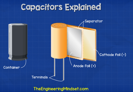
Working principle of capacitor: let us consider a parallel plate capacitor with a dielectric between them as shown in the below circuit. Now, apply the voltage V as shown in the circuit, plate 1 has the positive charge and plate 2 has negative charge. Across the capacitor an electric field appears.

How do capacitors work? Circuit Diagram
The decoupling capacitor absorbs unexpected spikes in the voltage of the signal, and if the voltage decreases, the capacitor supplies energy to stabilize it. It is critical for integrated circuits (IC). Bypass capacitor. A bypass capacitor filters high frequency from the signal. Bypass capacitor gives shortcuts to high frequencies to ground.

Learn how capacitors store electrical energy by separating conductors with an insulator and how they are used in various electronic devices. Find out how to measure capacitance and what factors affect it.

What Is a Capacitor: Types and Working Principle Circuit Diagram
Working Principle of a Capacitor. As we know that when a voltage source is connected to conductor it gets charged say by a value Q. And since the charge is proportional to the voltage applied, we can say that: Q∝V. In order to equate the charge Q and voltage V. Learn how a capacitor works by storing charge on its plates and acting as a source of electrical energy. See how a capacitor behaves in DC and AC circuits with diagrams and explanations. Learn what a capacitor is, how it stores electric charge and how it works with dielectric material. See examples of capacitor applications in decoupling, AC to DC conversion, signal filtering and energy storage.
