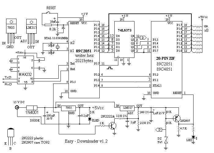
Unveiling the Secrets of Microcontroller Microprocessor electronics Circuit Diagram The brain of the system is the STM32H7 microcontroller. All sensors, ethernet TOE shield, and the camera are directly connected to the STM32 microcontroller. Sensors provide the data to STM32 microcontroller, the microcontroller uses the WIZnet W5300 ethernet module to forward the data to a cloud server using the MQTT protocol.

An advanced home automation project with Arduino Uno and Bluetooth sensor to control it, anytime from anywhere.

W5300 & STM32 Based Smart Home Hub Circuit Diagram
By integrating various devices and systems in a home, automation systems allow users to control and monitor their home environment remotely. This article explores the development of an IoT-based home automation system using a PIC Microcontroller, focusing on the key components, design, and implementation steps.Components of the System1. PIC Micr Different ESP32 projects with Blynk, IFTTT, Amazon Alexa, Google Home on Home Automation & Internet of Things. Explained with Circuit & Source Code.

Home automation gives you access to control devices in your home from a mobile device and other device anywhere in the world. The heart of device is programmable microcontroller devices, like Arduino, Raspberry pi, BeagleBone Black, SparkCore, DigiSpark, DigiSpark, ExtraCore system, but home automation more accurately describes homes in which nearly everything -- Room light, cooling AC, Motors By using ESP32 microcontrollers, LEDs, servo motors, and either a Raspberry Pi or your laptop, you'll gain the skills to build a complete home automation system with this project-based course. This course emphasizes industry-standard tools and best practices, making it an excellent resource for beginners and experienced developers alike.

How to Make a Simple Home Automation System Circuit Diagram
To build a smart home automation system using Arduino, you will need the following components: - Arduino UNO - Relay module - HC 05 Wireless Bluetooth Module - Lamp - 2.2k ohm resistor

In this project, we'll delve into creating a sophisticated IoT-based home automation system using the ESP32 microcontroller. This allows users to control three home appliances with voice commands via Google Assistant and Alexa. By following the steps outlined below, you'll be able to craft your own smart home ecosystem tailored to your needs. Let's get started. Step 1: Setting Up the If the internet is not available, then you can control the home appliances from manual switches. During the article, I have shown all the steps to make this home automation system. This ESP32 control smart relay has the following features: 1. Control home appliances with WiFi (Blynk App) 2. Control home appliances with manual switches. 3.
